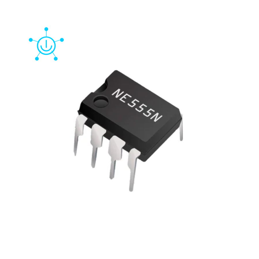
NE555 TIMER IC
Overview
NE555 / LM555 Timer IC — one of the most versatile and widely used integrated circuits ever manufactured. A precision timing IC capable of operating as a monostable multivibrator (one-shot timer), astable multivibrator (oscillator/clock generator), or bistable multivibrator (flip-flop). Used in millions of applications including LED flashers, PWM generators, tone generators, delay circuits, pulse generators, motor speed control, and signal processing. Compatible with 5V to 15V supply, making it suitable for Arduino, ESP32, and standalone circuits.
Specifications
| Parameter | Value |
|---|---|
| Model | NE555 / LM555 / SE555 |
| Type | Precision Timer IC |
| Supply Voltage | 4.5V – 16V |
| Output Current | 200mA (source/sink) |
| Timing Accuracy | ±1% |
| Temperature Stability | 0.005% per °C |
| Operating Frequency | DC to 500kHz |
| Output Voltage (HIGH) | VCC – 1.7V |
| Output Voltage (LOW) | 0.1V |
| Trigger Current | 0.5μA |
| Reset Current | 0.1mA |
| Power Dissipation | 600mW |
| Package | DIP-8 (Through-hole) |
| Operating Temperature | 0°C to +70°C (NE555) |
| Military Grade | -55°C to +125°C (SE555) |
Pin Configuration
| Pin | Name | Description |
|---|---|---|
| 1 | GND | Ground (0V) |
| 2 | TRIG | Trigger input — starts timing when < 1/3 VCC |
| 3 | OUT | Output — HIGH or LOW depending on state |
| 4 | RESET | Reset (active LOW) — tie to VCC if unused |
| 5 | CTRL | Control voltage — tie 10nF cap to GND if unused |
| 6 | THRES | Threshold — stops timing when > 2/3 VCC |
| 7 | DISCH | Discharge — open collector output for timing capacitor |
| 8 | VCC | Power supply (4.5V – 16V) |
Operating Modes
Mode 1 — Astable (Oscillator / Clock Generator)
Continuously oscillates — generates square wave output. No external trigger needed. Used for LED flashers, tone generators, PWM.
Frequency Formula: f = 1.44 / ((R1 + 2×R2) × C) Duty Cycle = (R1 + R2) / (R1 + 2×R2) × 100%
Astable Circuit: VCC ── R1 ── Pin7 ── R2 ── Pin2/6 │ C ── GND Pin4 (RESET) → VCC Pin5 (CTRL) → 10nF → GND
Mode 2 — Monostable (One-Shot Timer)
Outputs a single pulse of defined duration when triggered. Used for delay circuits, debouncing, pulse stretching.
Pulse Width Formula: T = 1.1 × R × C
Example: R=10kΩ, C=10μF → T = 1.1 × 10,000 × 0.00001 = 0.11 seconds
Monostable Circuit: VCC ── R ── Pin6/7 │ C ── GND Pin2 (TRIG) ── Button ── GND (trigger on LOW pulse) Pin4 (RESET) → VCC Pin5 (CTRL) → 10nF → GND
Mode 3 — Bistable (Flip-Flop / Latch)
Output latches HIGH or LOW based on trigger and reset inputs. Used for switch debouncing, latching circuits.
Pin2 (TRIG) ── Button1 ── GND (SET) Pin4 (RESET) ── Button2 ── GND (RESET) No timing components needed
Timing Reference Table (Monostable)
| R Value | C Value | Pulse Width |
|---|---|---|
| 10kΩ | 1μF | 11ms |
| 10kΩ | 10μF | 110ms |
| 10kΩ | 100μF | 1.1s |
| 100kΩ | 10μF | 1.1s |
| 1MΩ | 10μF | 11s |
| 1MΩ | 100μF | 110s |
Frequency Reference Table (Astable)
| R1 | R2 | C | Frequency |
|---|---|---|---|
| 1kΩ | 1kΩ | 100nF | 4.8kHz |
| 10kΩ | 10kΩ | 100nF | 480Hz |
| 10kΩ | 10kΩ | 10μF | 4.8Hz |
| 1kΩ | 47kΩ | 10μF | 1.5Hz |
| 10kΩ | 100kΩ | 100μF | 0.07Hz |
LED Flasher Circuit (Astable)
VCC (9V) │ R1 (1kΩ) │ Pin8 (VCC) ──────────── VCC Pin4 (RESET) ─────────── VCC Pin1 (GND) ───────────── GND Pin7 (DISCH) ── R1(1kΩ) ─── VCC Pin7 (DISCH) ── R2(47kΩ) ── Pin2/6 Pin2/6 ── C(10μF) ─── GND Pin5 (CTRL) ── 10nF ─────── GND Pin3 (OUT) ── 470Ω ─ LED ─ GN
Flash rate: ~1.5Hz (slow blink)
Arduino Integration
Use 555 timer with Arduino for:
- Hardware PWM independent of Arduino processor
- High current LED driving (200mA vs Arduino's 40mA)
- Precise timing without software delays
- Motor speed control via hardware PWM
// Read 555 output frequency with Arduino
int pin555 = 2; // Connect 555 OUT to pin 2
volatile int count = 0;

void countPulse() { count++; }

void setup() {
  Serial.begin(9600);
  attachInterrupt(digitalPinToInterrupt(pin555), countPulse, RISING);
}

void loop() {
  count = 0;
  delay(1000);
  Serial.print("Frequency: ");
  Serial.print(count);
  Serial.println(" Hz");
}
PWM Motor Speed Control
VCC ── R1(1kΩ) ── Pin8 Pin7 ── R2(10kΩ pot) ── Pin2/6 Pin2/6 ── C(100nF) ── GND Pin3 (OUT) ── MOSFET Gate ── Motor Pin4,8 ── VCC Pin5 ── 10nF ── GND
Adjust pot R2 to vary PWM duty cycle and motor speed.
555 vs 556 vs 558
| IC | Timers | Package | Notes |
|---|---|---|---|
| NE555 | 1 | DIP-8 | Standard single timer |
| NE556 | 2 | DIP-14 | Dual 555 in one package |
| NE558 | 4 | DIP-16 | Quad timer |
| LMC555 | 1 | DIP-8 | CMOS version, lower power |
| ICM7555 | 1 | DIP-8 | CMOS, works from 2V |
NE555 vs LM555 vs SE555
| Version | Temp Range | Grade |
|---|---|---|
| NE555 | 0°C to +70°C | Commercial |
| LM555 | 0°C to +70°C | Commercial (TI) |
| SA555 | -40°C to +85°C | Industrial |
| SE555 | -55°C to +125°C | Military |
⚠️ Important Notes
- Pin 4 (RESET) — always tie to VCC if not used, or IC will not work
- Pin 5 (CTRL) — connect 10nF bypass capacitor to GND to reduce noise
- Output current 200mA — can directly drive LEDs, small relays, buzzers
- Timing capacitor — use non-polarized capacitor for small values, electrolytic for large
- Electrolytic capacitor polarity — positive lead to Pin 2/6, negative to GND
- Decoupling capacitor — add 100nF between VCC and GND near IC
- Maximum frequency — 500kHz, higher freq use CMOS version (LMC555)
- Avoid touching Pin 5 — sensitive control voltage input
- For 3.3V operation — use CMOS 555 (LMC555 or ICM7555), NE555 needs min 4.5V
Applications
- LED flasher and blinker circuits
- Tone and sound generator
- PWM motor speed control
- Servo signal generator
- Debounce circuit for buttons
- Delay timer relay control
- Pulse width modulator
- Clock signal generator
- Missing pulse detector
- Frequency divider
- Metronome and rhythm generator
- Touch switch circuit
- Dark/light activated switch
- Battery level indicator
- Arduino hardware timer extension
៛1,000
Fast Shipping
Phnom Penh & provinces
7 Day Returns
Hassle-free returns