Atoms
Sn74Hc164N
Overview
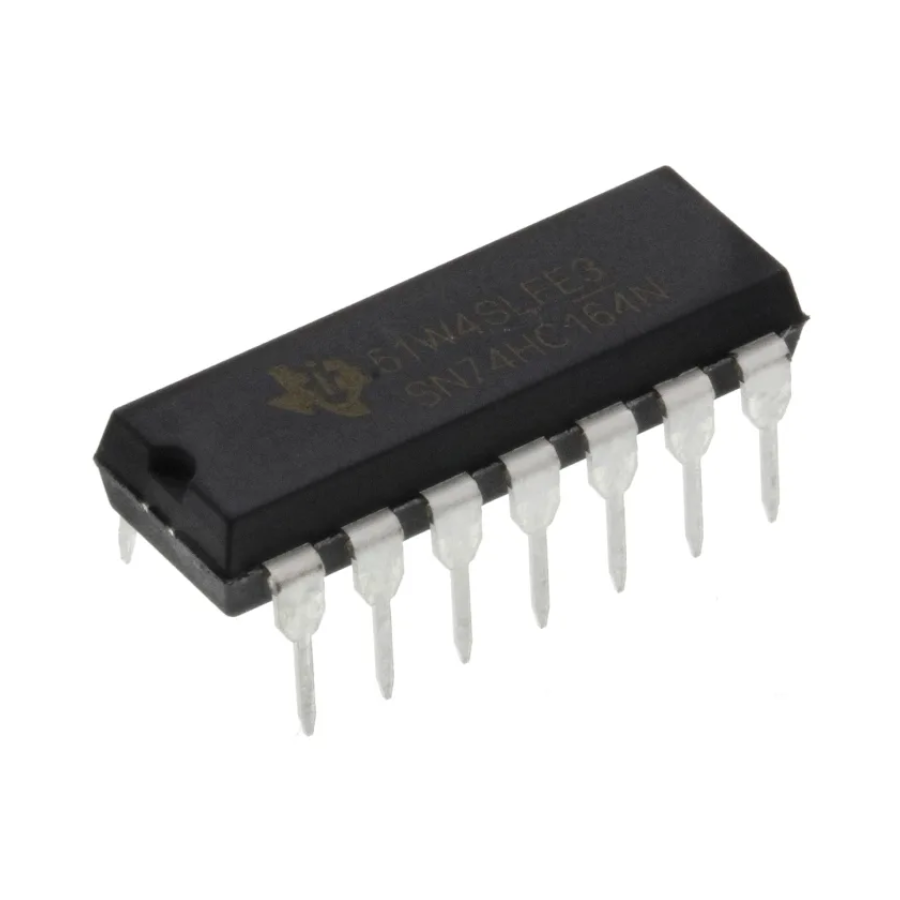
SN74HC164N 8-Bit Serial-In Parallel-Out (SIPO) Shift Register by Texas Instruments. A high-speed CMOS logic IC used for serial-to-parallel data conversion in digital electronics, LED matrix control, 7-segment displays, port expansion, and embedded systems. Compatible with Arduino, ESP32, STM32, Raspberry Pi, and all 5V/3.3V logic systems.
Specifications
| Parameter | Value |
|---|---|
| Model | SN74HC164N |
| Type | 8-bit SIPO Shift Register |
| Manufacturer | Texas Instruments |
| Supply Voltage | 2V – 6V |
| Logic Family | HC (High-Speed CMOS) |
| Clock Frequency | Up to 25MHz @ 5V |
| Output Type | Push-Pull (Totem-Pole) |
| Inputs | Serial Data (A, B) + Clock + Clear |
| Outputs | 8 parallel outputs (QA–QH) |
| Package | DIP-14 (Through-hole) |
| Propagation Delay | ~15ns @ 5V |
| Operating Temperature | -40°C to +125°C |
| Output Current | ±25mA per pin |
Pin Configuration
| Pin | Name | Description |
|---|---|---|
| 1 | A | Serial data input A |
| 2 | B | Serial data input B |
| 3 | QA | Parallel output bit 0 |
| 4 | QB | Parallel output bit 1 |
| 5 | QC | Parallel output bit 2 |
| 6 | QD | Parallel output bit 3 |
| 7 | GND | Ground |
| 8 | CLK | Clock input |
| 9 | CLR | Clear (active LOW) |
| 10 | QE | Parallel output bit 4 |
| 11 | QF | Parallel output bit 5 |
| 12 | QG | Parallel output bit 6 |
| 13 | QH | Parallel output bit 7 |
| 14 | VCC | Power supply (2V–6V) |
Features
- 8-bit serial to parallel conversion — expand GPIO with just 3 pins
- High-speed CMOS — up to 25MHz clock frequency
- AND-gated serial inputs — data = A AND B (tie together for single input)
- Synchronous clear — CLR pin resets all outputs low
- Wide voltage range — 2V to 6V operation
- DIP-14 package — breadboard and PCB friendly
- Cascadable — chain multiple ICs for 16, 24, 32-bit expansion
- Low power consumption
- TTL compatible inputs
Wiring (Arduino)
| SN74HC164N | Arduino |
|---|---|
| VCC (pin 14) | 5V |
| GND (pin 7) | GND |
| A (pin 1) | Data pin (e.g. pin 11) |
| B (pin 2) | Data pin (tie to A) |
| CLK (pin 8) | Clock pin (e.g. pin 13) |
| CLR (pin 9) | 5V (or GPIO for reset) |
| QA–QH | LEDs / Load |
Wiring (ESP32)
| SN74HC164N | ESP32 |
|---|---|
| VCC (pin 14) | 3.3V |
| GND (pin 7) | GND |
| A (pin 1) | GPIO23 (DATA) |
| B (pin 2) | GPIO23 (tie to A) |
| CLK (pin 8) | GPIO18 (CLK) |
| CLR (pin 9) | 3.3V |
Arduino Code Example
int dataPin = 11;
int clockPin = 13;

void setup() {
  pinMode(dataPin, OUTPUT);
  pinMode(clockPin, OUTPUT);
}

void shiftOut(byte data) {
  for (int i = 7; i >= 0; i--) {
    digitalWrite(dataPin, (data >> i) & 1);
    digitalWrite(clockPin, HIGH);
    delayMicroseconds(1);
    digitalWrite(clockPin, LOW);
  }
}

void loop() {
  shiftOut(0b10101010); // Alternating pattern
  delay(500);
  shiftOut(0b11110000);
  delay(500);
}
Cascading Multiple ICs
Connect QH (pin 13) of first IC to A (pin 1) of second IC. Share the same CLK and CLR signals. Result: 16-bit output with only 3 microcontroller pins.
⚠️ Notes
- Tie A and B together for single data line input
- Keep CLR HIGH during normal operation
- Add 100nF decoupling capacitor between VCC and GND near IC
- For 3.3V systems (ESP32) — operates correctly at 3.3V
- Do NOT exceed 25mA per output pin
Applications
- LED bar graph and matrix control
- 7-segment display driving
- GPIO port expansion
- Serial communication protocols
- Data latching and buffering
- Light chaser / sequencer circuits
- Relay bank control
- Arduino / ESP32 output expansion
$0.13$0.10Save $0.03
៛400
100 in stock
Quantity
1
🚚
Fast Shipping
Phnom Penh & provinces
↩️
7 Day Returns
Hassle-free returns